Dendritic arm spacing in aluminum alloy
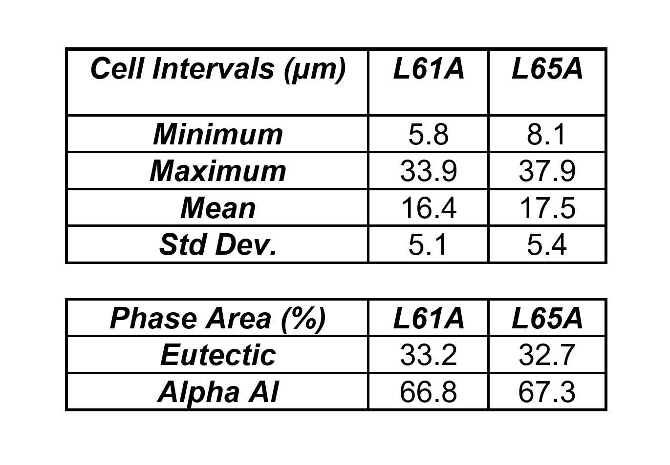
Two samples of Al alloy 357 from two different heats (L61 and L65) are submitted for dendrite arm spacing measurement.
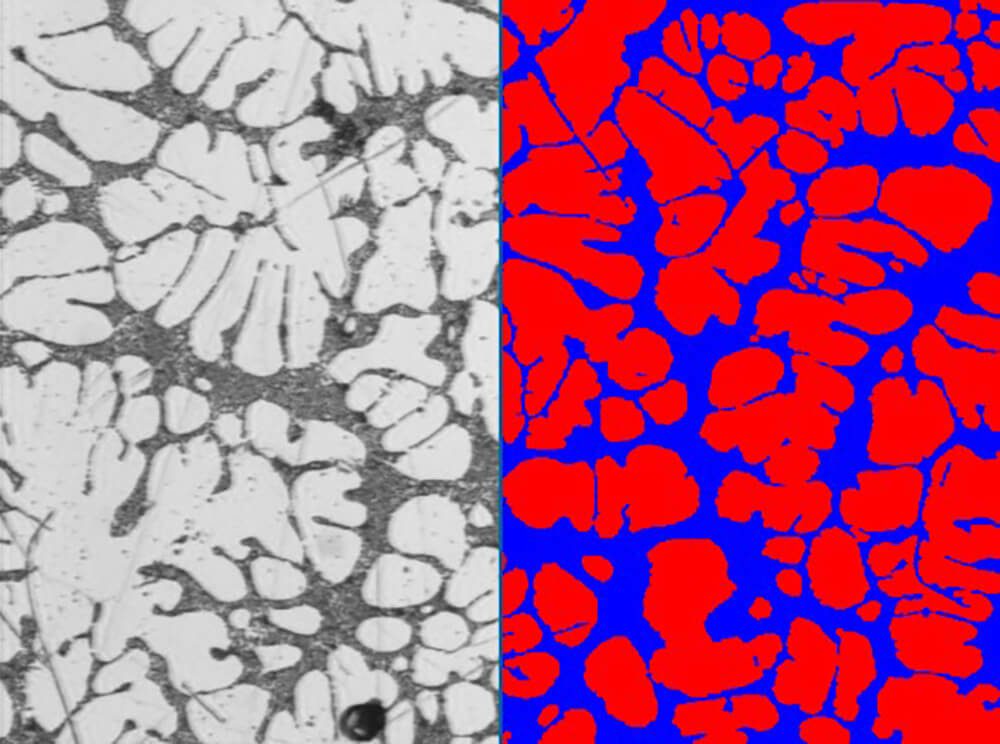
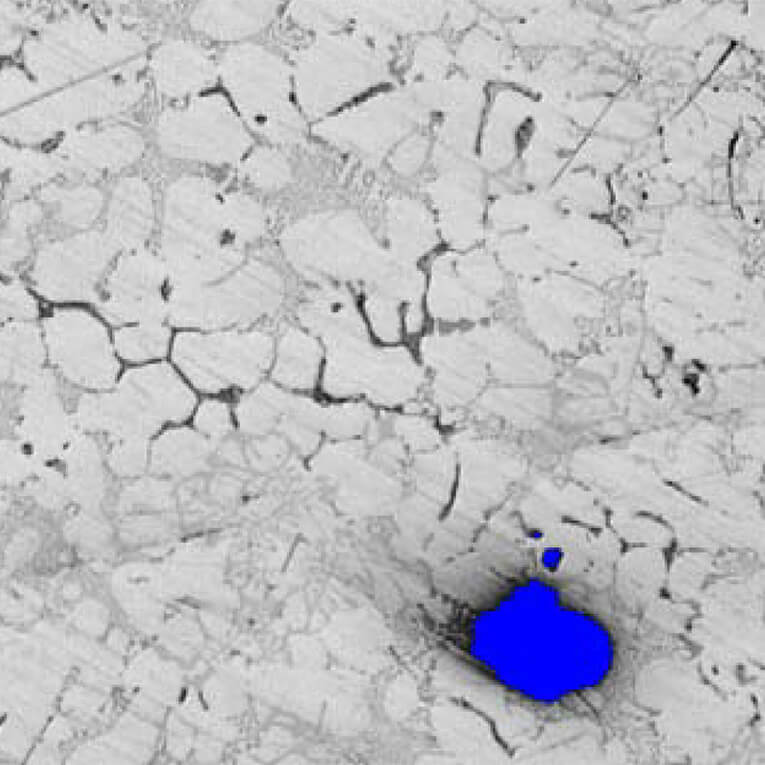
Figure 1. Original image from sample L61 at 200X. The eutectic is binarized into blue bitplane. The alpha aluminum phase (red) is deduced from the blue bitplane.
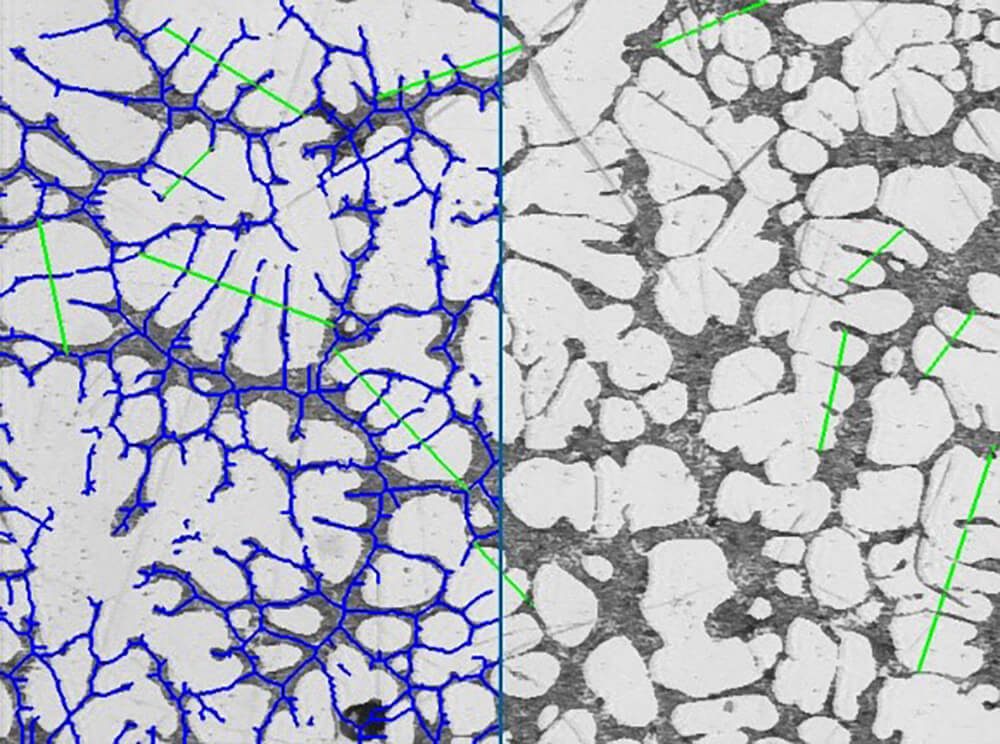
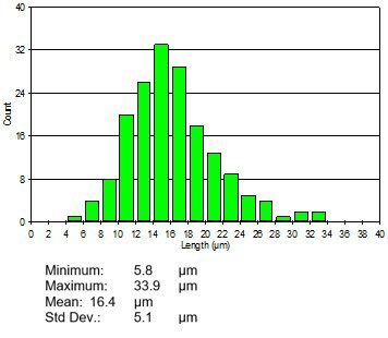
Figure 2. The blue bitplane is thinned to obtain the center between cells. A Pause Edit Line allows the user to draw properly oriented lines (green) over the dendrites. The lines are sectioned using the blue bitplane as reference. The green lines represent the cell intervals.
PURPOSE
Demonstrate the ability of the Clemex Vision image analysis system can measure the dendrite arm spacing in the field of view. The methods and operations used are discussed in the report linked at the bottom of this page (click the Download PDF link below).
RESULTS
Well polished surface is essential to minimize the influence of scratches when identifying the cell intervals. Analyzing multiple fields could give more representative results. Final results can be printed directly from Clemex Vision. Raw data are linked to their respective objects for validation purpose. Raw data can also be exported in Excel format.


