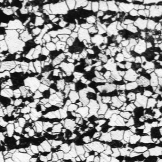
Dendrite Arm Spacing (DAS) Module
Dendrite arm spacing is one of the most widely used indicators of microstructural fineness in cast metallic alloys, and a well-established way to relate solidification conditions to final material quality. Clemex's dendrite arm spacing module supports the full range of measurement approaches, from fully manual annotation to a fully automated routine, so labs can choose the level of automation that fits their throughput and repeatability requirements.
Measure the fineness of your dendrite spacing. Use the manual or semi-automatic DAS routines, or jump to the fully automated MLDS method for a 16x faster alternative.
See It In Action
Dendrite Arm Spacing Module in Motion
Analysis Workflow
A General Dendrite Arm Spacing Workflow
Regardless of which mode is used, dendrite arm spacing measurement in Clemex Vision follows the same underlying workflow, and only the amount of operator involvement changes.
Capture / load the image
An image of the polished sample is captured live through the microscope, or a previously saved image is loaded, at a known magnification and calibration factor.
Detect phases
The relevant phase or matrix is isolated into a reference bitplane, which serves as the basis for identifying dendrites.
Draw & measure
Depending on the selected mode, the operator draws lines or intersections by hand; separations and measurements are then automated.
Generate report
Results update instantly in the results panel and generate a report for further processing or sharing.
Analysis Modes
Three Ways to Measure Dendrite Arm Spacing
Clemex Vision supports three modes of analysis within the same dendrite arm spacing module, so the amount of automation can be matched to the task at hand.
Fully Manual Measurement
The operator captures the image and measures dendrite arms directly using on-screen measurement tools, with no assisted detection. This offers full control, at the cost of speed and consistency between operators.
Semi-Automatic DAS Routine
The relevant phase is binarized to guide the operator, who then draws or annotates lines over dendrite arms or cell intervals. The length distribution updates instantly in the results panel and can be exported through a Linear Intercept Method macro.
Operator-guidedFully Automated MLDS Routine
An image analysis routine automatically detects dendrites and superimposes a set of concentric circles, exporting measurements of overlapped features with no manual tracing required.
Up to 16x fasterChoosing the Analysis Mode
Manual vs. Semi-Automatic vs. Automated
Within the DAS routine, both the manual and semi-automatic modes adapt to how the dendrite arms or cells are arranged in the field of view: aligned arms are measured through line intercepts, while randomly oriented, equiaxed cells are measured through circle intercepts. What changes between the two modes is how much of that process the operator performs by hand versus how much Clemex Vision completes automatically. The fully automated MLDS routine removes manual tracing altogether.
| 1 · Manual (DAS) | 2 · Semi-Automatic (DAS) | 3 · Automated (MLDS) | |
|---|---|---|---|
| Best suited for | Aligned dendrite arms, or randomly oriented cells, regardless of contrast | Aligned dendrite arms, or randomly oriented cells, with clear boundaries and good phase contrast | Any dendritic microstructure, across magnifications and cameras |
| What the operator draws | Lines and their intersections over the dendrite arms or cells | Lines only over aligned arms, or intersections only over detected cells | Nothing; detection and circle placement are automatic |
| What's automatic | Only the final separations and measurements | Intersections, separations, and measurements | Dendrite detection, circle overlay, separations, and measurements |
| Measurement basis | Line section or spacing, from manually separated intercepts | Spacing, width, or arc section, depending on arm or cell arrangement | Concentric circle intercepts, converted to mean linear dendrite spacing |
| Speed | Slowest | Baseline | Up to 16x faster |
What Gets Measured
Metrics Computed by the DAS Module
Whichever mode is used, the module builds a statistical picture of dendrite fineness across the sample rather than relying on a single measurement.
Distribution Statistics
Spacing & Spread
Mean spacing
The average dendrite arm spacing (or cell interval / dendrite cell spacing) across all measured features in a field.
Minimum & maximum
The smallest and largest measured spacings, useful for spotting outliers or unusually coarse regions.
Standard deviation
Quantifies how consistent the spacing is across the sample and across fields.
Microstructure Context
Phase & Confidence
Phase area percent
The proportion of the field occupied by the eutectic, matrix, or dendrite phase, giving context to the spacing values.
Dendrite arm aspect ratio
Describes the elongation of dendrite arms, complementing spacing data with a shape indicator.
95% confidence interval
Reported alongside each statistic to show how representative the result is, especially as more fields are analyzed.
Analyzing multiple fields per sample, rather than a single field, produces a more statistically representative result and a tighter confidence interval, regardless of the measurement mode used.
Dendrite Arm Spacing Analysis Examples
Where the DAS Module Is Used
Real micrographs and analysis reports from the Clemex Vision dendrite arm spacing module, spanning the manual, semi-automatic, and automated modes.
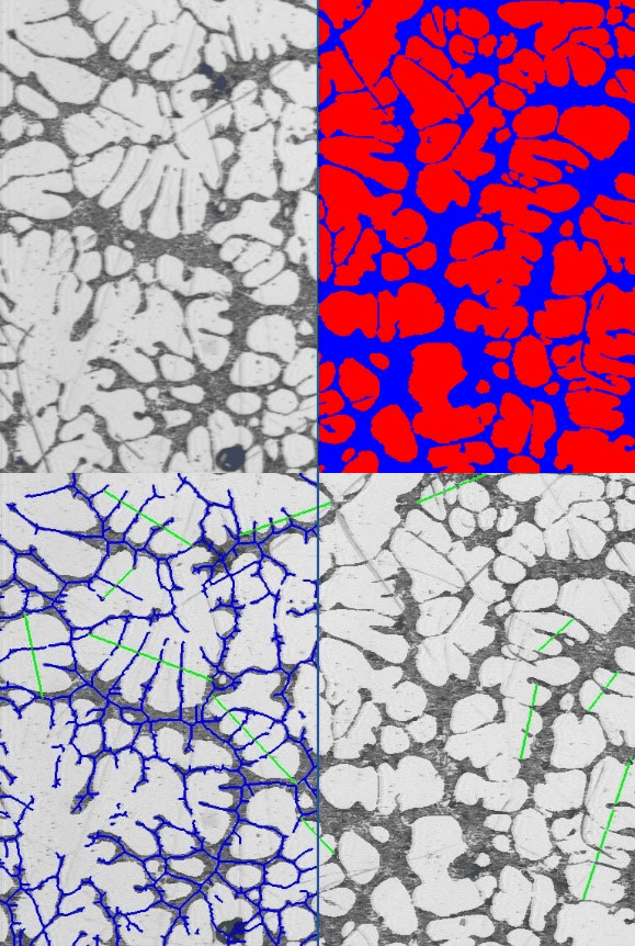
Aluminum Alloy 357
Original micrograph alongside its binarized eutectic (blue) and alpha aluminum (red) phases, used to derive dendrite cell intervals across two heats of the same alloy.
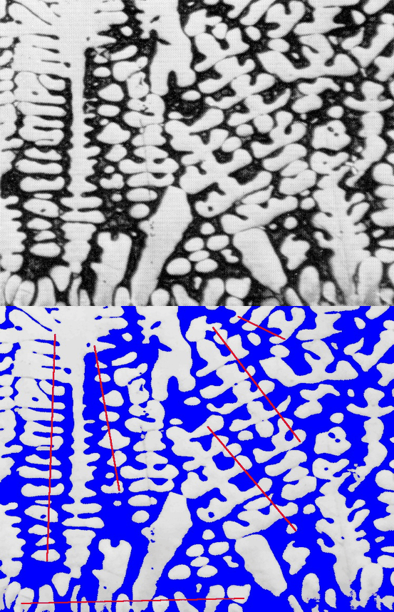
Dendritic Copper-Lead Alloy
The lead matrix is binarized and the operator draws straight lines through the dendrite arms; only the segments crossing the matrix are kept for measurement.
Cast Aluminum Alloy
Dendrites are automatically detected across the field, feeding a mean linear dendrite spacing calculation with no manual line-drawing required.
Frequently Asked Questions
What is dendrite arm spacing (DAS) and why does it matter?
DAS quantifies the fineness of the dendritic microstructure in cast metallic alloys. Finer spacing is generally associated with faster solidification and better mechanical properties, making DAS a key quality indicator in castings.
What's the difference between the manual, semi-automatic, and automated modes?
The manual mode relies entirely on the operator to capture and measure. The semi-automatic (DAS) mode binarizes the relevant phase to guide the operator, who then draws or annotates lines over dendrite arms. The automated (MLDS) mode detects dendrites and overlays concentric circles automatically, with no manual tracing.
Is the automated MLDS mode equivalent to manual DAS measurements?
Yes. MLDS has been shown to be equivalent to traditional DAS values while being up to 16 times faster and less prone to operator subjectivity, since the same routine is applied consistently regardless of who runs the analysis.
Does the module work on alloys other than aluminum?
Yes. The same underlying workflow and set of measurement modes applies across hypoeutectic casting alloys, dendritic bearing alloys, and other cast metallic microstructures where dendrite fineness is a relevant indicator.
Why does surface polish matter for this analysis?
A well-polished surface is essential to minimize the influence of scratches when identifying dendrite boundaries, in every measurement mode.
How many fields should be analyzed per sample?
Analyzing multiple fields produces a more statistically representative result and a tighter confidence interval around the mean spacing, regardless of which measurement mode is used.
Ready to Measure Dendrite Arm Spacing?
Talk to a Clemex expert about the manual, semi-automatic, and automated routines, or request a live demo on your own sample images.